Division of Integrative Systems and DesignHKUST
← All research stories

Understand / 2026

Magnetic friction

Explaining an unexpected friction curve.

THE CENTRAL QUESTION

Why can magnetic friction become largest at an intermediate separation rather than at the strongest attraction?

Friction is often explained by how strongly two surfaces press or attract. From that viewpoint, pulling magnetic layers farther apart should make friction fall smoothly. The experiment instead found a pronounced maximum at an intermediate distance. To understand that counterintuitive curve, the project built a visible model interface in which every microscopic-like element could rotate and be tracked during sliding.

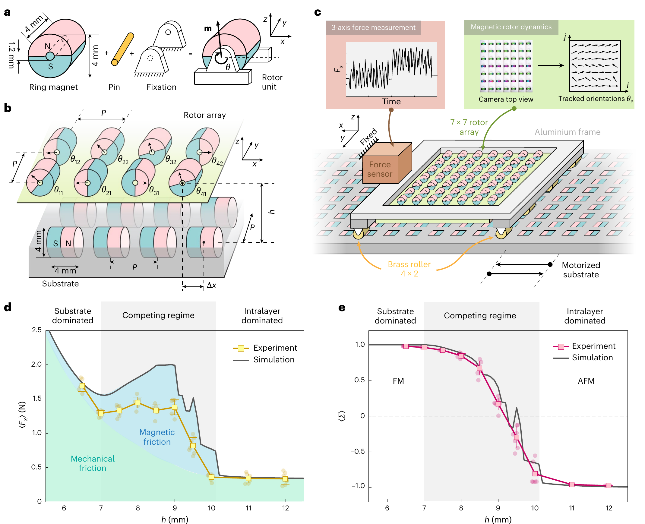
A rotor array slides over a magnetic substrate while lateral force and collective order are measured.
A rotor array slides over a magnetic substrate while lateral force and collective order are measured. Cropped from Fig. 1 of the linked paper.
01

An anomaly hidden by the usual explanation

Magnetic attraction decreases steadily as the two layers are separated, but the measured sliding force does not. It rises, reaches a maximum near a particular spacing and then falls. The peak therefore cannot be explained by load or attraction alone; something inside the moving layer must change.

02

A friction interface whose internal motion is visible

The upper layer is a 7 by 7 array of freely rotating permanent-magnet bars. It slides above a fixed magnetic substrate while a three-axis sensor records lateral force and a camera records the orientation of every rotor. Unlike atoms at a real interface, these millimetre-scale elements can be observed individually.

03

Competing orders meet at the friction peak

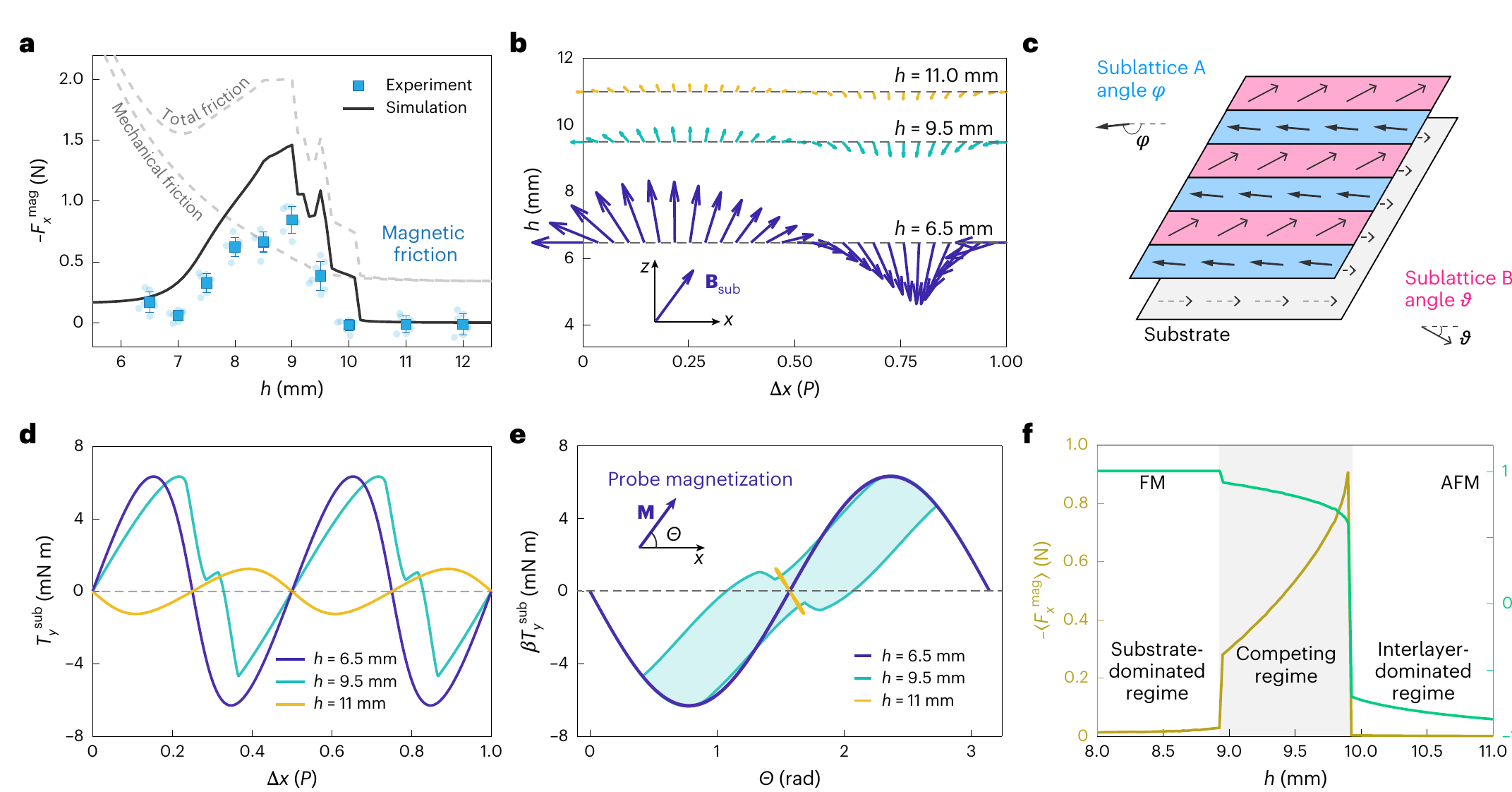
At small separation, the substrate encourages neighbouring rotors to alternate direction, producing antiferromagnetic order. Farther away, interactions within the rotor layer favour parallel, ferromagnetic alignment. Near the crossover, neither tendency wins cleanly, and the array repeatedly reorganizes as it slides.

A reduced two-sublattice model links hysteretic torque cycles to peak dissipation.
A reduced two-sublattice model links hysteretic torque cycles to peak dissipation. Cropped from Fig. 4 of the linked paper.
04

How reorganization dissipates energy

Molecular-dynamics calculations and a simplified two-sublattice model reproduce the peak. The rotors do not follow the magnetic torque along the same path forward and backward; they trace a hysteresis loop. The area of that loop represents energy lost during each cycle, linking the observed collective switching to friction.

05

What the model system contributes

The study turns friction into a readout of collective order and suggests a route to tunable, contactless dissipation. It is a millimetre-scale, commensurate and strongly damped analogue, not a direct replica of an atomic surface. Applying the mechanism at other scales will require systems that preserve the same competition and switching dynamics.